|
• Wavelength dispersive spectrometers |
|
|
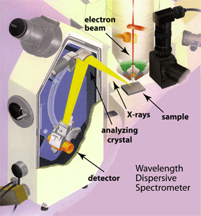
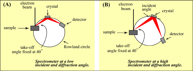
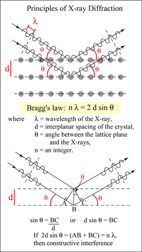
Regularly spaced atoms in a crystal structure can diffract X-rays. This means that X-rays hitting a crystalline material will re-radiate in a particular direction under certain conditions. The direction and conditions are defined by Bragg's law. The parameters that define whether diffraction will occur are the wavelength of the X-rays, the incident angle of the X-rays, and the interplanar spacing within the crystal. If diffraction occurs, the X-rays leaving the crystal will be in phase, and the departure angle will be equal to the incident angle. A geometric explanation for this phenomenon can be seen in the diagram to the right. The lower ray in each figure must travel a farther distance than the upper. If the extra distance (A-B-C) is exactly an integer number of wavelengths (1,2,3 ...) then the two X-rays will leave in-phase. If the distance A-B-C is not an integer number of wavelengths, the two rays will be out of phase, destructive interference will occur, and the X-rays will be absorbed by the material. One can see that for a given d-spacing (the interplanar spacing of the crystal), the distance A-B-C can be changed by changing the incident angle. In a wavelength dispersive spectrometer, the incident angle can be changed by moving the crystal around the Rowland circle. Therefore at each position a different wavelength of X-rays will diffract, and only those X-rays that diffract will enter the detector. Because of the physical limitations of the spectrometers, no single crystal can diffract all of the X-rays produced from the elements in the periodic table. Each crystal will only be able to diffract a certain range of wavelengths. Therefore WD spectrometers will have a number of crystals to choose from depending on the elements being analyzed. |
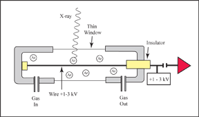
The counter itself is a cylinder filled with a gas. The gas is separated from the vacuum of the instrument by a thin window. The X-ray photon enters through this window where it knocks out electrons from the electron shells of the gas molecules. These electrons are attracted to a wire running down the center of the detector, which has a positive 1-3 kV potential on it. The electrons hitting the wire produce a current which is picked up by the preamp and then turned into a signal. The amount of current is proportional to the number of X-rays that are entering the detector. |
In the Xenon counter, the gas in the cylinder is Xenon, and the cylinder is sealed. The window that separates the detector from the vacuum is beryllium. Because the window is made of beryllium, low-energy X-rays from light elements can get absorbed. Therefore this type of detector is only used in spectrometers with LIF and PET crystals, where higher energy X-rays will be analyzed. For low-energy X-ray work, the gas flow proportional counter will give a higher count rate. The windows on these counters are made from a thin polymer. They are thin enough to allow the low-energy X-rays to enter; yet they are strong enough to withstand the difference in pressure between the vacuum and the atmospheric pressure inside the counter. However, they are thin enough that the gas will slowly leak through the membrane. To over come this, these counters have the gas flowing through them continuously. The gas used is P10, a mixture of argon and methane. |
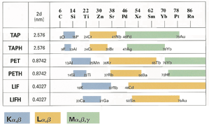
The TAP, PET, and LIF crystals cover most of the periodic table with the exception of the light elements (Table 2). Their names are abbreviations of their compositions. • TAP = thallium acid phthalate LDE crystals are used for light elements. They are not actually crystalline materials, but are layered synthetic microstructures. They are manufactured by depositing alternating layers of heavy and light elements (like carbon and tungsten). The layers are very thin, on the order of 50-150 A, and act like lattice planes in a crystal structure. Since they are manufactured, the LDE crystals can be fine tuned to diffract specific elements. The listed d-spacings in Table 1 for the LDE crystals are approximates only, as each crystal is slightly different. |
Table 1. Comparison of the commonly
|
